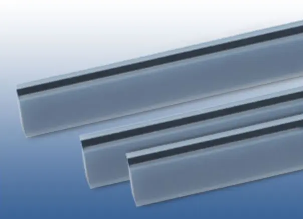
The YS type conductive rubber connectors are supported by insulating silicone rubber on both sides of the zebra layer to meet applications with insulation requirements. At the same time, because the insulation layer is softer than the zebra layer, good contact performance can be achieved in practical applications with only a small compressive force.
YS type conductive rubber connector insulation lining is silicone natural color (transparent), can also be made according to the requirements of white, green and other colors.
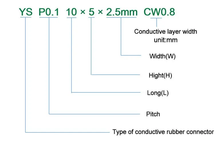
To ensure that conductive rubber connectors are made correctly, the naming conventions are as follows:
The superior elasticity of conductive rubber connectors can effectively avoid the risk of good contact with components due to aging deformation and accidental drop of structural parts during the use of electronic equipment, but with the deformation of structural parts and the change of compression force, the compression ratio and resistance of conductive rubber connectors will also change, and it is necessary to fully consider when setting structural parts and conductive rubber connectors. As follows:
Spline: YS P0.1 10×5×2.5mm CW0.8
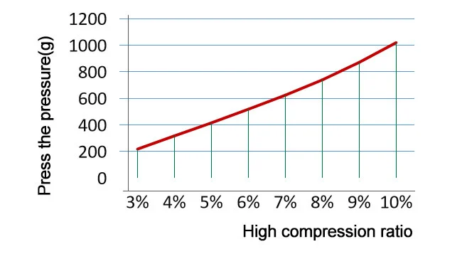
Relationship between compressive force and compression ratio
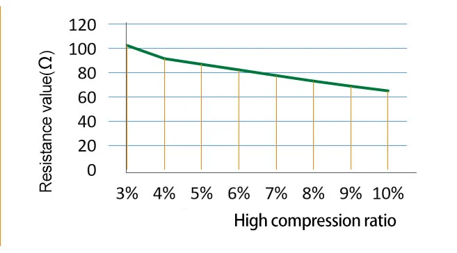
Resistance vs. compression ratio

R = Resistance value (Ω)
CW = Conductive width (mm)
L = Conductive length (mm)
H = Conductive height (mm)
ρ = volume resistivity (Ω·cm)
The testing process should maintain a compression ratio of >5% to obtain accurate test results.

F = Compressive force (g)
D = Compression ratio D = (H-H1) ÷ H
E0 = Fully conductive layer modulus of elasticity 3.5MPa
E1 = Modulus of elasticity of the insulation liner 1.1MPa
H = Conductive rubber connector height (mm)
W = Conductive rubber connector width (mm)
CW = Fully conductive layer width (mm)
W1 = Insulation liner width (mm) W2= W-W1
L = Conductive rubber connector length (mm)
Implementation standard: GB2439, GB/T528
| Project | Specification values | |||
| Material | Conductive layer | Insulation layer | Insulating lining | |
| Conductive silicone rubber | Silastic | Silastic | ||
| Routine | Low resistance | Routine | Routine | |
| Hardness(A) | 65±5 | 70±5 | 65±5 | 30±5 |
| Volume resistivity(Ω·cm) | <6 | <3 | >1012 | >1012 |
| Overhang length(mPa) | >4 | >5 | >4 | >4 |
| Elongation(%) | >100 | >150 | >100 | >300 |
| Tear strength(N/mm) | >8 | >12 | >10 | >12 |
| Color | Black | White | Transparent/white | |
| Operating temperature | Operating humidity(%)25℃ | Maximum current used (mA/mm2) | |
| Minimum | Maximun | ||
| -50 | 150 | 85 | 2.5 |
-

 Keypads & Buttons
 Protective Covers
 LSR Overmolding
 Seals & Gaskets
 Conductive Zebra Strips
 Other Silicone Components
 Financial & Payment
 Consumer Electronics
 Industrial Control
 Beauty & Personal Care
 Medical & Healthcare
 Others