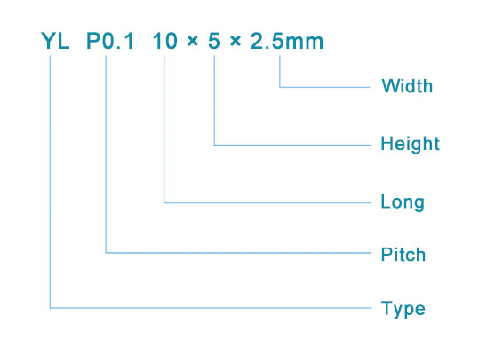
Naming conventions
To ensure that elastomeric connectors are made correctly, the naming conventions are as follows:
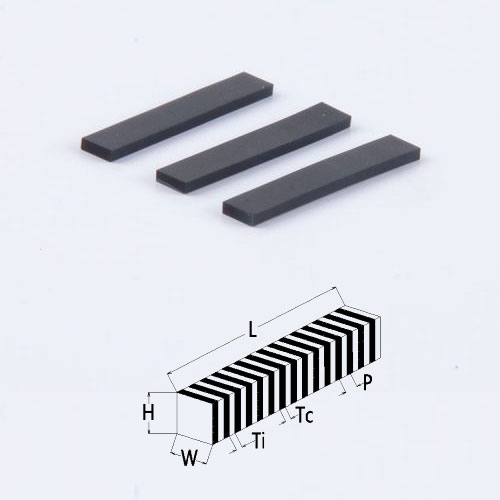
Preload relationship and curve
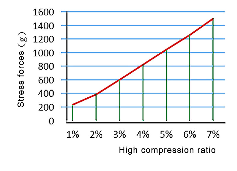
The superior elasticity of elastomeric connectors can effectively avoid the risk of good contact with components due to aging deformation and accidental drop of structural parts during the use of electronic equipment, but with the deformation of structural parts and the change of compression force, the compression ratio and resistance of elastomeric connectors will also change, and it is necessary to fully consider when setting structural parts and elastomeric connectors. As follows:
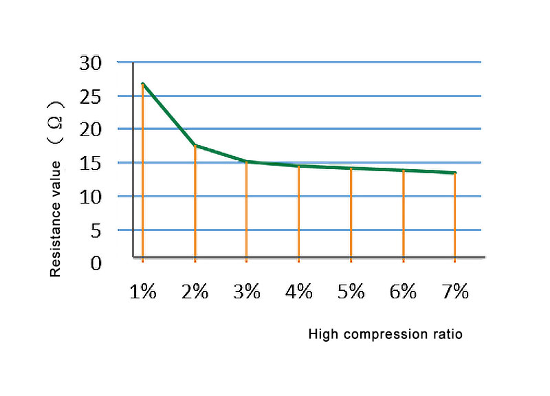
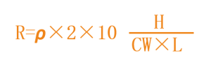
The calculation of conductive rubber connector resistance can be referenced by the following formula:
The calculation of the compressive force of a conductive rubber connector can be calculated by reference to the following formula:

F = Compressive force (g)
E = Modulus of elasticity: 4.4 (MPa)
D = Compression ratio D = (H-H1) ÷H
H = Conductive rubber connector height (mm)
W = Conductive rubber connector width (mm)
L = Conductive rubber connector length (mm)
Structure and electrical performance data
Implementation standard: GB2439, GB/T528
| project | Specification values | |||
| Material | Conductive layer | Insulation layer | ||
| Conductive silicone rubber | Silastic | |||
| Routine | Low resistance | Routine | ||
| Hardness(A) | 65±5 | 70±5 | 65±5 | |
| Volume resistivity(Ω·cm) | <6 | <3 | >1012 | |
| Tensile strength(mPa) | >4 | >5 | >4 | |
| Elongation(%) | >100 | >150 | >100 | |
| Tear strength(N/mm) | >8 | >12 | >10 | |
| Color | Black | White | ||
Work environment data
| Operating temperature | Operating humidity(%)25℃ | Maximum current used (mA/mm2) | |
| Minimum | Maximun | ||
| -50 | 150 | 85 | 2.5 |